Components of Induction Heating
Elements of Induction Heating
A typical induction heater system includes a power supply, impedance matching circuit, tank circuit, and applicator. The applicator which is the induction coil can be a part of the tank circuit. A tank circuit is usually a parallel set of capacitors and inductors. The capacitor and inductor in the tank circuit are reservoirs of electrostatic energy and electromagnetic energy, respectively. At the resonance frequency, the capacitor and the inductor start to swing their stored energy to each other. In the parallel configuration, this energy conversion occurs at high current. The high current through the coil helps to have a good energy transfer from the induction coil to the workpiece.
Click here to learn what induction coils are and how they work, and the different types of coils.
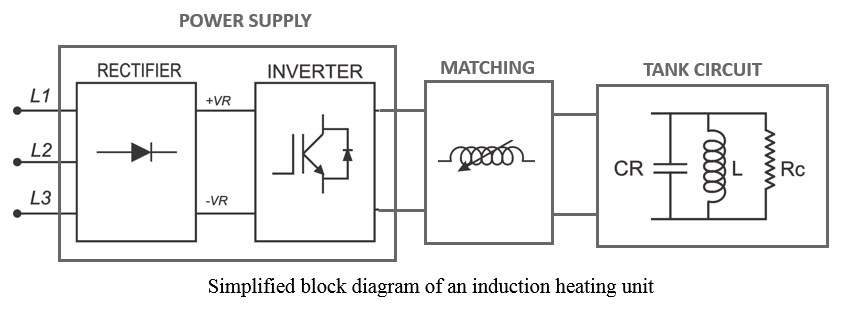
 a) Power Supply
Power supplies are one of the most important parts of an induction heater system. They are typically rated by their operating frequency range and power. There are various types of induction power supplies which are line-frequency supplies, frequency multipliers, motor-generators, spark-gap converters, and solid-state inverters. Solid-state inverters have the most efficiency between the power supplies.
A typical solid-state inverter power supply includes two major sections; Rectifier and Inverter. Line ac currents are converted into dc in the rectifier section using diodes or thyristors. The dc current goes to the inverter, where solid-state switches, such as IGBTs or MOSFETs convert it into a current, this time at a high frequency (typically in the range of 10kHz-600kHz). According to the diagram below, IGBTs can work at a higher power level and lower frequency versus MOSFETs operating at a lower power level and higher frequencies.
b) Impedance Matching
Induction heating power supplies, like every other electronic device, have maximum voltage and current values which should not be exceeded. In order to deliver the maximum power from the power supply to the load (workpiece), the impedance of the power supply and the load must be as close as possible. In this way, the power, voltage and current values can reach their highest allowed limits simultaneously. Impedance matching circuits are used in induction heater units for this purpose. According to the application, different combinations of electrical elements (e.g. transformers, variable inductors, capacitors, etc.) can be used.
c) Resonance Tank
The resonance tank in an induction heating system is normally a parallel set of capacitor and inductor which resonates at a certain frequency. The frequency is obtained from the following formula:

where L is the inductance of the induction coil and C is the capacitance. According to the animation below, the resonance phenomenon is very similar to what happens in a swinging pendulum. In a pendulum, kinetic and potential energies convert to each other while it swings from one end to another. The motion is damped due to the friction and other mechanical losses. In the resonance tank, the energy provided by the power supply oscillates between the inductor (in the form of electromagnetic energy) and the capacitor (in the form of electrostatic energy). The energy is damped due to the losses in the capacitor, inductor, and the workpiece. The losses in the workpiece in the form of heat are desired and the goal of induction heating.
The resonance tank itself includes the capacitor and inductor. A bank of capacitors is used to provide the needed capacitance in order to reach a resonance frequency close to the capability of the power supply. At low frequencies (below 10kHz) oil-filled capacitors and at higher frequencies (more the 10kHz) ceramic or solid dielectric capacitors are used.

d) Induction Heater Inductors
What Are Induction Coils & How Do They Work?
The induction heating coil is specifically shaped copper tubing or other conductive material which alternating electrical current is passed through, creating a variable magnetic field. Metal parts or other conductive materials are placed within, through or close to the induction heating coil, without touching the coil and the variable magnetic field that is generated causes a friction within the metal causing it to heat.
How Do Induction Coils Work?
Some conditions need to be considered when designing a coil:
1. In order to increase the induction heaters efficiency, the distance between the coil and the workpiece must be minimized. The efficiency of the coupling between the coil and the workpiece is inversely proportional to the square root of the distance between them.
2. If the part is positioned at the center of the helical coil, it will be best coupled to the magnetic field. If it is off-center, the area of the workpiece closer to the turns will receive more heat. This effect has been shown in the figure below.

3. Also, the position close to the leads-coil connection has a weaker magnetic flux density, therefore even the ID center of the helical coil is not the induction heating center.
4. The cancellation effect (figure on the left) must be avoided. This happens when the opening of the coil is very small. Putting a loop in the coil will help to provide the necessary inductance (figure on the right). The inductance of an inductor defines the capability of that inductor to store magnetic energy. Inductance is can be calculated from as:

where ε is the electromotive force and dI/dt is the rate of the current change in the coil. ε itself is equal to the rate of the magnetic flux change in the coil (- dφ/dt), where the magnetic flux φ can be calculated from NBA, with N being the number of turns, B the magnetic field and A the area of the inductor. Therefore the inductance will be equal to:

It is obvious that the value of the inductance is linearly proportional to the area of the inductor. Hence, a minimum value must be considered for the inductor loop, so that it can store magnetic energy and deliver it to the induction workpiece.

Coil Efficiency
The coil efficiency is defined as follows:

The table below shows typical efficiencies of different coil:

Coil modification according to the application
In several applications, the heating object does not have a uniform profile, though needs uniform heating. In these cases, the magnetic flux field needs to be modified. There are two typical methods to accomplish this. One way is to decouple the turns where the part has a bigger cross-section (if using helical coil). A more common method is to increase the winding inter-spacing at the areas where the part cross-section is larger. Both methods are shown in the figure below.

The same situation happens when heating flat surfaces with large pancake coils. The central area will get excessive heat. To avoid this, the gap between the coil surface and the flat object will be increased by applying a conical shape to the pancake coil.

A coil with liner is used in applications where a wide and uniform heating area is needed, but we want to avoid using large Copper tubing. Liner is a wide sheet which is tack brazed to the coil tubing at least in two point. The rest of the joint will be soldered only to provide the maximum heat transfer connection. Also a sinusoidal profile will help to increase the cooling capability of the coil. Such a coil is shown in the figure below.

As the heating length increases, the number of turns must be increased in order to keep the heating uniformity.

Depending on the changes of the shape of the workpiece, the heating pattern vary. Magnetic flux tend to accumulate at the edges, surface cuts or indentations of the heating object, thus causing higher heating rate in these areas. Figure below shows the “edge effect” where the coil is higher than the edge of the heating element and excessive heating happens at this area. To avoid this, the coil can be brought lower, to be even or slightly lower than the edge.

Induction heating of disks can also cause excessive edge heating, as shown in the figure below. The edges will get higher heating. The height of the coil can be reduced or the ends of the coil can be made out of a bigger radius to decouple from the edge of the workpiece.

Sharp corners of the rectangular coils can cause deeper heating in the workpiece. Decoupling the corners of the coil on one hand will reduce the heating rate of the corner, but on the other hand decreases the overall efficiency of the induction process.

One of the important items to be considered while designing multiplace coils is the effect of the adjacent coils on each other. In order to keep the heating strength of each coil at maximum, the center-to-center distance between the adjacent coils must be at least 1.5 times the coil diameter.

Split inductors are used in the applications where a close coupling is needed and also the part cannot be extracted from the coil after the heating process. An important point here is that a very good electrical contact must be provided at the place where the hinged surfaces meet. Usually, a thin silver layer is used to provide the best surface electrical contact. The split parts of the coils will be cooled down using flexible water tubing. Automated pneumatic compression is often used to close/open the coil and also to provide the needed pressure at the hinged area.

Types of Heating Coils
Double Deformed Pancake Coil
In the applications like heating the tip of shafts, reaching a temperature uniformity can be difficult because of the cancellation effect at the center of the surface of the tip. A double deformed pancake coil with tilled sides, similar to the scheme below, can be used to achieve uniform heating profile. Attention must be paid to the direction of the two pancakes, in which the central windings are wound in the same direction and have adding magnetic effect.

Split-Return Coil
In the applications like welding a narrow band on one side of a long cylinder where a relatively long length must be heated considerably higher than the other areas of the object, the current return path will be of importance. Using the Split-Return type of coil, the high current induced in the welding path will be divided into two which will be even wider. This way, the heating rate at the welding path is at least four times higher than the rest of the parts of the object.

Channel Coils
Channel type of coils is used if the heating time is not very short and also fairly low power densities are needed. A number of heating parts will pass through the coil at a constant speed and reach their maximum temperature when getting out of the machine. The ends of the coil are usually bent in order to provide the path for the parts to enter and exit the coil. Where a profile heating is needed, plate concentrators can be used with multiturn channel coils.

Square Copper tubing has two main advantages compared to the round tubing: a) since it has a more flat surface “looking” at the workpiece, it provides a better electromagnetic coupling with the heating load and b) it is structurally easier to implement turns with square tubing rather than round tubing.

Lead Design for Induction Coils
Lead Design: Leads are a part of the induction coil and although they are very short, they have a finite inductance. In general, the diagram below shows the circuit diagram of the heat station of an induction unit system. C is the resonance capacitor installed in the heat station, L_lead is the total inductance of the leads of the coil and L_coil is the inductance of the induction coil coupled with the heating load. V_total is the voltage applied from the induction power supply to the heat station, V_lead is the voltage drop on the lead’s inductance and V_coil is the voltage which will be applied to the induction coil. The total voltage is the summation of the lead’s voltage and the induction coil’s voltage:

V_lead represents the amount of the total voltage that is occupied by the leads and does not do any useful induction action. The designer’s goal will be to minimize this value. V_lead can be calculated as:

It is obvious from the formulae above that in order to minimize the value of V_lead, then the inductance of the leads must be several times smaller than the inductance of the induction coil (L_lead≪L_coil).

Lead Inductance Reduction: At low frequencies, usually since high inductance coils (multiturn and/or big ID) are used, L_lead is much smaller than L_coil. However, since the number of turns and the overall size of the coil reduces for high frequency inductors, then it will become important to apply special methods to minimize the lead’s inductance. Below there are two examples to accomplish this.

Flux Concentrators: When a magnetic material is placed in the environment including magnetic fields, due to the low magnetic resistance (reluctance) they tend to absorb the lines of magnetic flux. The ability of absorbing the magnetic field is quantified by Relative Magnetic Permeability. This value for air, Copper and stainless steel is one, but for mild steel can go up to 400 and for Iron up to 2000. Magnetic materials can keep their magnetic capability up to their Curie temperature, after which their magnetic permeability drops to one and they will not be magnetic anymore.
A flux concentrator is a high permeability, low electrical conductivity material that is designed to be used in construction of the induction heater coils to magnify the magnetic field applied to the heating load. The figure below shows how placing a flux concentrator at the center of a pancake coil will concentrate the magnetic field lines at the surface of the coil. Thus the materials placed on top of the pancake coil will couple better and will receive the maximum heating.

The effect of flux concentrator on the current density in the induction coil is shown in the figure below. Most of the current will be concentrated on the surface which is not covered with flux concentrator. Therefore the coil can be designed in such way the that only the side of the coil facing the heating load will be left without the concentrator materials. In electromagnetism, this is called slot effect. Slot effect will increase the efficiency of the coil significantly and the heating will need a lower power level.

Reference:
- S. Zinn and S. L. Semiatin, “Elements of Induction Heating, Design, Control and Applications”, A S M International, ISBN-13: 9780871703088, 1988